
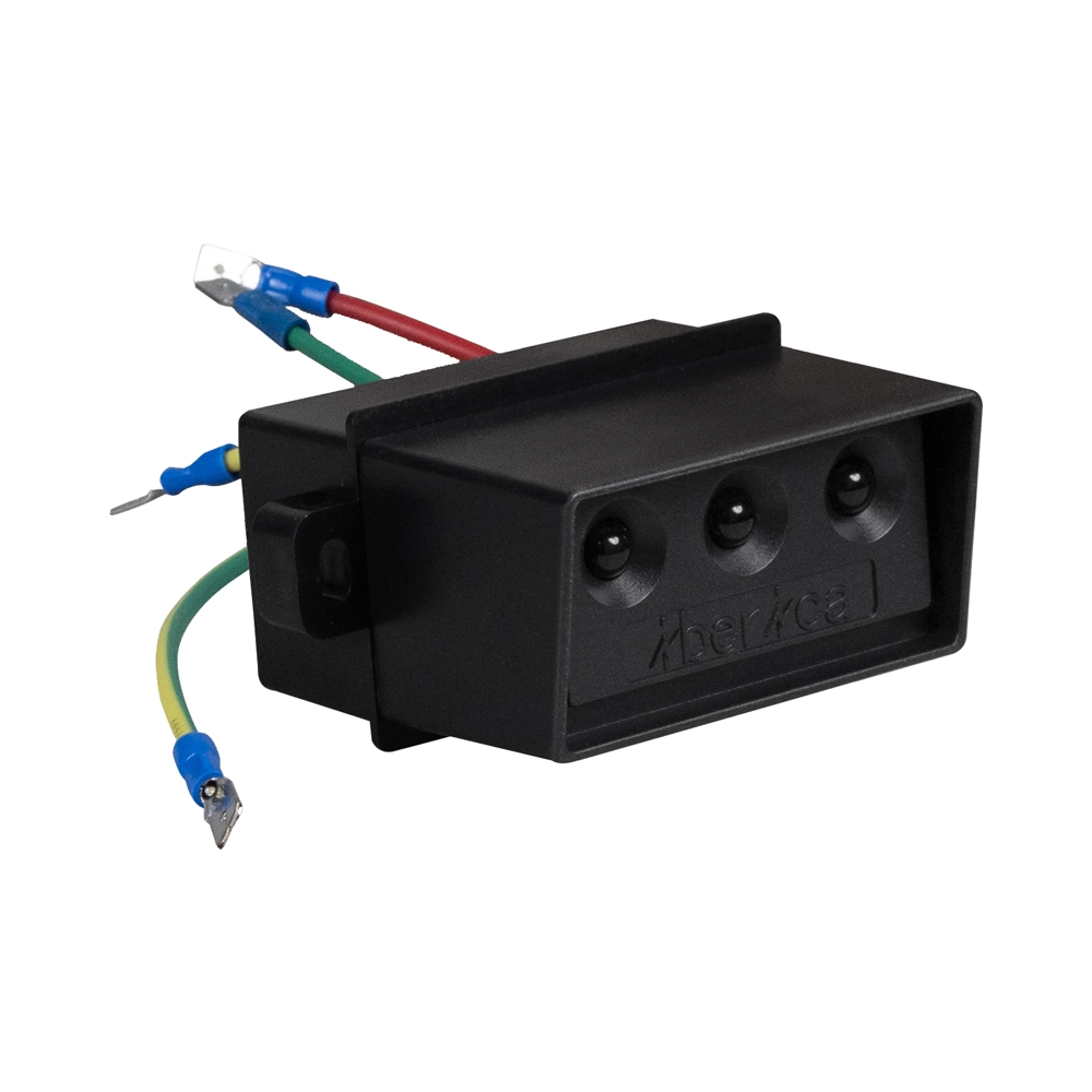
Medium-voltage switchgear requires careful handling because energized conductors can create serious electrical hazards. Personnel need reliable information about voltage conditions before performing inspections, switching operations, or maintenance tasks. A VPIS Indicator provides visible information about voltage presence through an integrated indication system. This information helps operators recognize potentially energized phases and make more informed operational decisions. However, indication alone cannot establish whether equipment is safe to touch. Electrical safety depends on correct equipment design, reliable signals, established operating procedures, and appropriate verification methods. When integrated into a suitable switchgear assembly, voltage presence indication supports hazard awareness and reduces uncertainty during routine operations. Its value depends on correct installation, compatible components, and proper interpretation of the displayed signals.
What Is a Voltage Presence Indicating System?
A Voltage Presence Indicating System, commonly abbreviated as VPIS, provides a visual indication of voltage presence in electrical equipment. Manufacturers typically integrate these systems into medium-voltage switchgear and related distribution equipment. Capacitive coupling elements detect electrical signals from the relevant phases and transfer them to an indicating interface. Depending on the design, the interface may use illuminated indicators or other visual signals to represent phase conditions. Operators can check these signals without directly contacting energized conductors. Nevertheless, the system does not function as a precision voltmeter or independently verify the absence of hazardous voltage. Its primary purpose is to provide an accessible indication of electrical conditions. Personnel must interpret the display according to the manufacturer’s instructions and the equipment’s designated operating procedures.
How a VPIS Indicator Supports Electrical Safety
A VPIS Indicator helps personnel identify potential electrical hazards before they begin work around switchgear. Visible phase indications provide useful information during routine inspections, equipment checks, and switching activities. For example, an illuminated phase indicator may signal that the associated circuit remains energized. Operators can use this information to question unexpected conditions and investigate possible discrepancies before proceeding. The system also supports communication between maintenance teams and control-room personnel by providing a recognizable indication at the equipment location. However, an extinguished indicator does not necessarily prove that voltage is absent. Component failure, connection problems, or conditions outside the system’s intended operating range may affect the display. Personnel should therefore treat the indication as one source of operational information rather than definitive proof of electrical safety.
Key Components That Influence Indication Reliability
Reliable voltage indication depends on several interconnected components rather than the display alone. Capacitive coupling elements provide signals associated with the electrical phases. Connecting interfaces transfer those signals to the indicating unit, while the display communicates the resulting status to operators. Phase identification markings help personnel associate each indication with the appropriate conductor. Depending on the switchgear design, additional interfaces may support compatible voltage comparison or testing accessories. Damaged insulation, loose connections, contamination, or incompatible replacement components can compromise system performance. Incorrect wiring may also produce misleading indications or prevent the display from functioning correctly. Maintenance personnel should check the physical condition of accessible components and follow manufacturer-approved inspection procedures. Any suspected internal defect requires assessment by qualified personnel using appropriate safety precautions.
Where Voltage Presence Indication Is Commonly Used
Voltage presence indication commonly appears in medium-voltage switchgear, ring main units, and electrical distribution substations. These installations contain switching and protection equipment that distributes power across industrial facilities, commercial buildings, and utility networks. In a ring main unit, operators may check phase indications before carrying out authorized switching operations or investigating unexpected circuit conditions. Distribution substations can use similar systems to support routine operational checks and maintenance planning. Actual applications depend on the switchgear configuration, voltage class, and manufacturer’s design. Some installations require additional interfaces for voltage comparison or phase concordance checks. Other configurations provide only basic voltage presence indication. Engineers should verify the intended function before specifying equipment. The presence of an indicator does not automatically establish compatibility with every switching arrangement or safety procedure.
Selecting a VPIS Indicator for Compatible Switchgear
Selecting a VPIS Indicator requires careful attention to electrical compatibility, mechanical integration, and operating conditions. Engineers should verify the switchgear’s rated voltage, system frequency, phase configuration, and designated interface requirements. They should also confirm that the selected system matches the manufacturer’s specified capacitive coupling arrangement. Display dimensions, mounting provisions, and terminal configurations may affect installation and replacement. Environmental conditions deserve equal attention because temperature, humidity, contamination, and vibration can influence component performance. Documentation should identify the applicable product standards, testing requirements, and installation limitations. IEC 62271-213 addresses voltage detecting and indicating systems for rated voltages above 1 kV and up to 52 kV, subject to its defined scope and requirements. Procurement teams should verify the applicable edition and equipment conformity before approval. Compatibility should always take priority over appearance or interchangeability assumptions.
Practical Checks Before Installation and Operation
Before installation, engineers and maintenance teams should verify the equipment documentation and confirm that all specified components match the switchgear design. A structured checklist can help prevent omissions during inspection and commissioning.
- Confirm rated voltage, frequency, and phase configuration.
- Check the interface type and approved component compatibility.
- Inspect accessible connections, insulation, markings, and mounting arrangements.
- Verify installation requirements against the manufacturer’s documentation.
- Confirm the approved procedure for functional checks and maintenance.
- Record identified defects and corrective actions.
These checks establish a consistent process for assessing installation quality and operational readiness. They do not replace specialized commissioning tests or electrical safety procedures. Qualified personnel should perform any required testing with suitable equipment and approved work practices. If a display behaves unexpectedly, personnel should avoid relying on its indication until they resolve the discrepancy. Inspection records should identify the equipment, inspection date, observed condition, and necessary corrective measures. Consistent documentation also helps maintenance teams identify recurring problems and plan component replacement. Clear responsibilities reduce the risk of overlooked defects during handovers and scheduled maintenance activities.
Maintaining Reliable Voltage Indication Over Time
Routine maintenance helps preserve the reliability of voltage presence indication throughout the equipment’s service life. Inspection frequency should follow manufacturer recommendations, site maintenance policies, and applicable electrical safety requirements. During authorized inspections, personnel should look for visible damage, loose accessible connections, deteriorated insulation, and unclear phase markings. They should also investigate indicators that remain dark, flicker unexpectedly, or display inconsistent phase conditions. A failed visual signal does not automatically identify the underlying cause. Possible explanations include component damage, connection problems, or conditions affecting the sensing circuit. Corrective work must follow approved procedures and account for electrical hazards. Personnel should never remove covers or access internal components while equipment remains energized unless an explicitly authorized procedure permits the work. Maintenance records should document findings, repairs, replacement parts, and subsequent verification.
Why Voltage Indication Cannot Replace Electrical Isolation
Voltage presence indication supports hazard recognition, but it cannot independently establish a safe working condition. A dark display may result from a failed indicator, interrupted sensing connection, or other malfunction. Certain circuit conditions may also fall outside the system’s intended detection capabilities. Consequently, personnel must follow the site’s approved isolation procedure before accessing conductors or performing work that requires a de-energized circuit. This process generally includes identifying all relevant energy sources, operating the appropriate isolation devices, applying lockout/tagout controls where required, and preventing unintended re-energization. Qualified personnel must then verify the absence of voltage using a suitable, properly rated testing device and the prescribed verification procedure. Additional precautions, including grounding, may apply according to the equipment design and local requirements. The indicator provides supporting information, not authorization to touch electrical parts.
Integrating Voltage Indication into a Safety Program
Effective electrical safety requires coordinated controls rather than dependence on a single device. Equipment specifications should define the intended indication function, compatible interfaces, maintenance responsibilities, and relevant documentation. Operating procedures should explain how personnel interpret phase indications and respond to abnormal or missing signals. Training should also clarify the difference between voltage presence indication, voltage measurement, and verification of an electrically safe work condition. Supervisors can reinforce these distinctions through maintenance reviews, switching documentation, and periodic competency assessments. Procurement teams should obtain installation instructions, technical specifications, and conformity information before accepting replacement components. Maintenance departments should establish clear reporting routes for defective displays and unresolved discrepancies. When organizations combine appropriate equipment with disciplined procedures and qualified personnel, voltage indication can contribute meaningfully to electrical hazard awareness without creating false confidence.
FAQCan a VPIS Indicator Confirm That Electrical Equipment Is Safe to Touch?
No. A voltage presence display cannot independently confirm that electrical equipment is safe to touch. An illuminated signal can indicate potential voltage presence, but a dark signal does not prove that the circuit is de-energized. Component failures, sensing connection defects, and other abnormal conditions may affect the indication. Personnel must follow approved isolation procedures before performing work that requires de-energized equipment. These procedures include preventing unintended re-energization and verifying the absence of voltage with an appropriate, properly rated testing device. Additional grounding and protective measures may also apply. Qualified personnel must follow applicable regulations, site procedures, and manufacturer instructions. The display supports operational awareness, but it never replaces the required verification of a safe working condition.
What Is the Difference Between a VPIS and a Voltage Detector?
A VPIS is generally integrated into switchgear and provides a visual indication of voltage presence through a designated sensing interface. Its primary purpose is to give operators accessible information about electrical conditions at the equipment. A voltage detector, by contrast, is a broader term covering devices designed to detect voltage under specified conditions. Suitable testing instruments may support verification procedures when personnel need to establish whether conductors remain energized. However, not every voltage detector is suitable for proving a circuit dead. Device selection depends on the voltage level, equipment configuration, applicable standards, and intended task. Personnel should follow the prescribed testing procedure and verify the instrument’s operation as required. Neither device should be used beyond its specified capabilities.
How Often Should a VPIS Indicator Be Inspected?
Inspection frequency depends on manufacturer recommendations, operating conditions, maintenance policies, and applicable safety requirements. Some facilities incorporate visual checks into routine switchgear inspections, while other checks occur during scheduled maintenance or commissioning activities. Personnel should pay attention to damaged components, unclear markings, inconsistent signals, and unexpected display behavior. Any suspected defect requires assessment before personnel rely on the indication for operational decisions. Functional verification must follow the manufacturer’s approved method and the site’s electrical safety procedures. Organizations should also review inspection intervals after equipment modifications, abnormal operating events, or recurring failures. Records should document inspection findings, corrective actions, and component replacements. A consistent maintenance program helps identify developing problems while preserving the distinction between voltage indication and formal verification of electrical isolation.